How to prepare and AutoCAD drawings for setting out?
Posted by Philip Hanrahan B.E., B.A., M.I.E.I. on 15th Feb 2022
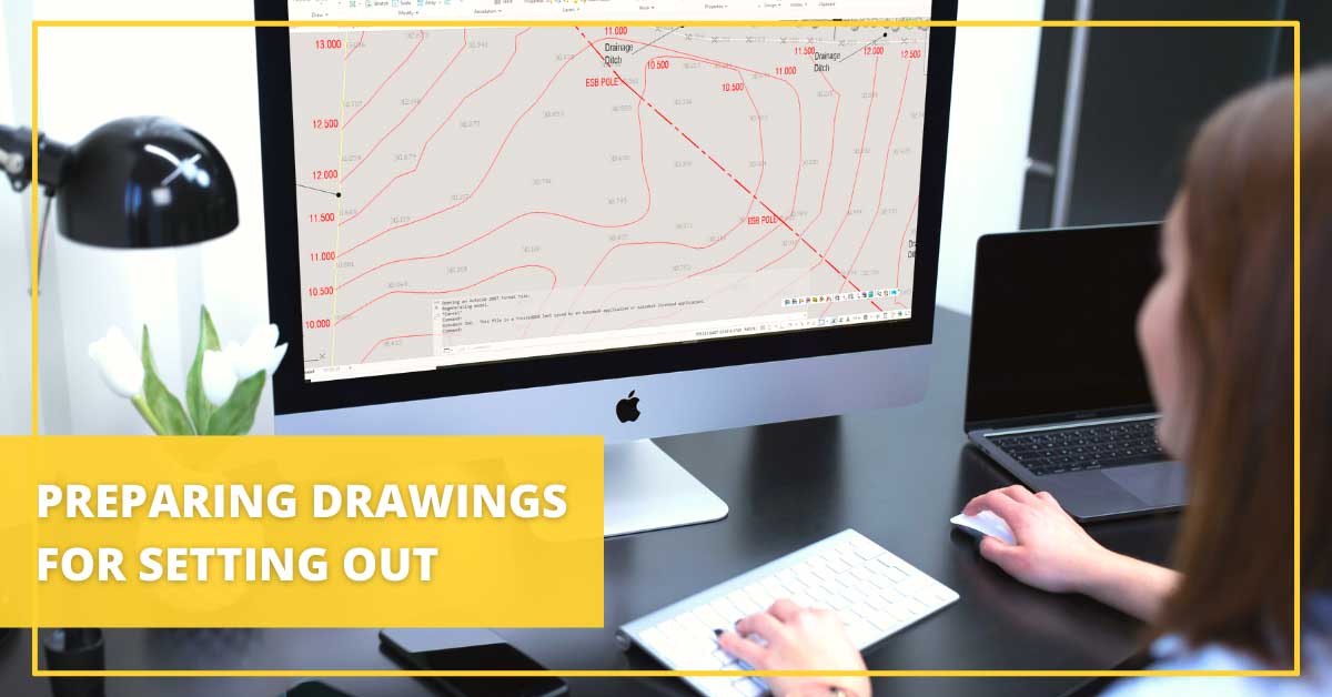
Frequently our technical support staff get queries from customers about loading drawings to their tablet or datalogger for setting out. Or the site engineer has arrived on site after loading a drawing and it isn't in the right place or the building line or feature that he wants to set out is not displayed or is in a block or has some other problem. The main issue usually is understanding exactly what is required in a drawing before you can go and set out.
Why you need to prepare drawings before staking out?
You can’t upload every drawing to a Total Station tablet or GNSS rover and go and stake out with it. Prior to uploading to the data logger, the drawing must be prepared. There are two reasons for this:
- Drawings prepared on the PC are using different software to the software on the data logger. Points, lines, objects are handled different in the different software packages. To exchange between one software package and another you need to save the file as a Drawing eXchange Format – a DXF file
- Dataloggers have significantly less processing and display power than a PC, so the drawing size needs to be less than that on the PC. (See no. 7 below)
What are minimum requirements for a drawing file?
The following details the minimum requirements that a drawing file will need before you upload it to the datalogger for setting out.
- Drawing should be in meters, not millimeters.
- Drawing should be layered, with Survey, Contours, Piles, Buildings, Roads, Footpaths, Foul, Storm, Roads, Greenery, Utilities, Boundaries, Walls, etc., etc. all on separate layers.
- Remove all the
following from the drawing:
- Legends, title boxes, drawing surrounds, explanatory text
- All hatching
- House or building internal fittings
- Unnecessary block, e.g., cars, road gullies, trees, road marking symbols, etc.
- Explode all objects, including nested objects.
- Remove complex line styles. Lines should be simple lines or polylines.
- Purge all unnecessary layers & blocks.
- The DXF (not DWG) file
size should be less than.
- 1Mb for handheld data loggers (generally 3.5” screen)
- 10Mb for tablet data loggers
- The file must be:
- For X-PAD software on the data logger any DXF or DWG version.
- For FieldGenius on the data logger software DXF must be R12/LT2 DXF
- If there is a lot of detail in the drawing when importing to X-PAD, turn off Object Vertices, as this will create points at every line intersection and end point and make the screen refresh slow.
What if you’re setting out with GNSS rover?
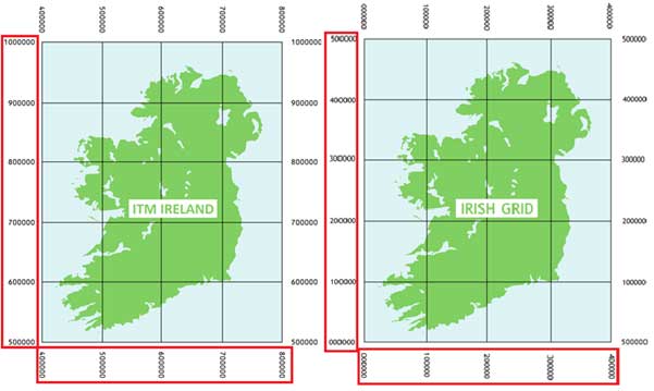
The additional ESSENTIAL requirement for setting out with the GNSS rover is that a drawing must be correctly georeferenced. i.e., coordinates of any point on the drawing must be in either Ireland ITM or Irish Grid and must match its physical position on the ground.
- You can check this in AutoCAD by doing ID POINT on any point – see approximate
position in these figures:
- And additionally by checking the actual position of the site boundaries against the drawing (stake out the boundaries).
Ready to start staking out?
Once you follow all the above steps, you can export your drawing to tablet or data logger and rest assured that all the required points will show where they’re supposed to. The file is now a proper size for your data logger, so it won’t freeze on you either.
---
Looking for more tips and step-by-step instructions? Visit our Downloads page.